Key Features
- Large Flow Rates (Up to 16 lbm/sec)
- Highly Repeatable Results (Less than ±0.25%)
- Measures airflow of large effective area (greater than 13 inch2 at PR = 1.05) passages in both aircraft and land-based turbine engine components (like Combustion Liners and Vane Segments)
- Small Footprint
- Dedicated Air Receiver Tank
- Uses a single, manually interchangeable sonic nozzle to measure flow
- Highly customizable controller software for test automation and data management
How does this flow controller work?
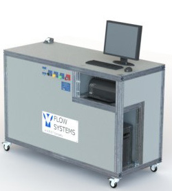
This test stand is a sonic nozzle (critical flow Venturis) based airflow test instrument for measuring the flow parameters of flow circuits. The test station contains critical flow Venturi manifolds, piping and pneumatic control hardware, a data acquisition and switching control hardware, pressure and temperature measurement instrumentation, and a computer with control software. The computer software handles the opening and closing of critical flow Venturi flow paths and calculates airflow rates based on sensor inputs. The software also monitors the airflow conditions to ensure the sonic nozzles are in a “choked” state and that the flow is stable. The software allows for generating, saving, and recalling test configuration data as well as configuring, saving and printing test results data.
Related Products for Measuring Different Flow Ranges
The Low Flow Air Test Stand is one in a series of air flow test stands designed for the aerospace and turbine engine-based component industries. These test stands are designed to provide complete, automated solutions for flow measurement.
Complies with OEM Test Specifications
OEMs and their suppliers worldwide require quality airflow measurement of passages in both aircraft and land-based turbine engine components. Each OEM has a unique testing specification and their suppliers must be flexible with the test procedures in order to comply with each OEM test specification. Accuracy, repeatability, throughput and availability are critical elements in the design of these test systems. These air flow test systems currently comply with the in-house testing procedures of ABB/Alstom Power, ABB Gas Turbines, Pratt & Whitney America, Pratt & Whitney Canada, General Electric Aircraft Engines (General Electric Infra, Aviation), General Electric Power Systems (General Electric Infra, Energy), Honeywell, Mitsubishi Power Systems, Mitsubishi Heavy Industries, Allison Engine, Rolls-Royce, Solar Turbines, Siemens, Siemens-Westinghouse, Snecma, and many others.
System Specifications
The Mega Flow Air Test Stand come in four configurations:
| Configuration | Air Mass Flow Range | Sonic Nozzle Throat Diameter |
|---|---|---|
| Conifuration A | 1.0 to 2.0 lbm/sec* | 1.414″ |
| Conifuration B | 2.0 to 4.0 lbm/sec* | 2.000″ |
| Conifuration C | 4.0 to 8.0 lbm/sec* | 2.828″ |
| Conifuration D | 8.0 to 16.0 lbm/sec* | 4.000″ |
* If Pressure Ratio Equals 1.049, multiply lbm/sec values above by 6.45 to estimate Effective Area in square inches.
Additional Specifications
| Specification | Value(s) |
|---|---|
| Part Pressure Ratio Range | 1.02 – 1.15, custom ranges available |
| Accuracy | ±0.48% of reading |
| Turndown | 2:1 |
| Repeatability | Less than ±0.25%, defined as 2 standard deviations divided by the mean of 20 samples |
| Cycle Time | 20 – 60 seconds, capacity dependent |
| Flow Ports Connections | Based on customer requirement |
| Pressure Connections | 1/4″ (-4) Swagelok Instrumentation Female Quick Connectors – QC series, color keyed |
| Dimensions | Based on customer requirements |
| Weight | Based on customer requirements |
